
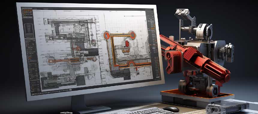
In sheet metal drafting and modeling, design engineers must juggle intricate geometries, formability predictions, materials’ properties, variability in responses of metals to bending and cutting, material springback, kerf adjustments for laser cutting, the limitations of fabrication techniques and equipment, and a host of other issues. Sheet metal CAD drafting and modeling processes often become too complex, making it tough to deliver efficient, accurate and cost-effective designs on time.
Table of Contents
- Tip 1: Implement Effective Part Identification
- Tip 2: Specify Hardware with Precision
- Tip 3: Adopt Rigorous Revision Control
- Tip 4: Consider Grain Direction in Design
- Tip 5: Define Powder Coating Specifications Clearly
- Tip 6: Optimize with SolidWorks Sheet Metal Module
- Tip 7: Explore SolidWorks Weldments for Structural Design
- Tip 8: Standardize Bend Radii for Efficiency
- Tip 9: Adhere to DFM/DFMA Principles
- Tip 10: Streamline Assembly Design For Ease of Manufacturing
Such challenges can be overcome to a great extent by preemptively considering fabrication pitfalls and adopting a first-time-right design approach with Design for Manufacture and Assembly (DFMA), Model-Based Definition (MBD), and Feature-Based Parametric Modeling (FBPM).
DFMA encourages proactive collaboration with fabricators, a shared commitment to upholding production standards and achieving optimal manufacturability, without compromising a design’s functional and aesthetic requirements.
However, when it comes to actually implementing these practices at work, inefficiencies crop up if considerations such as accuracy in part identification, hardware specifications, revision control, grain direction or standardizing bend radii are even slightly overlooked.
So, to help you save time, we have presented 10 practical tips to sharpen your techniques in the next sections of this article. They’ll help you create fabrication-ready sheet metal drafts and models with greater accuracy and efficiency.
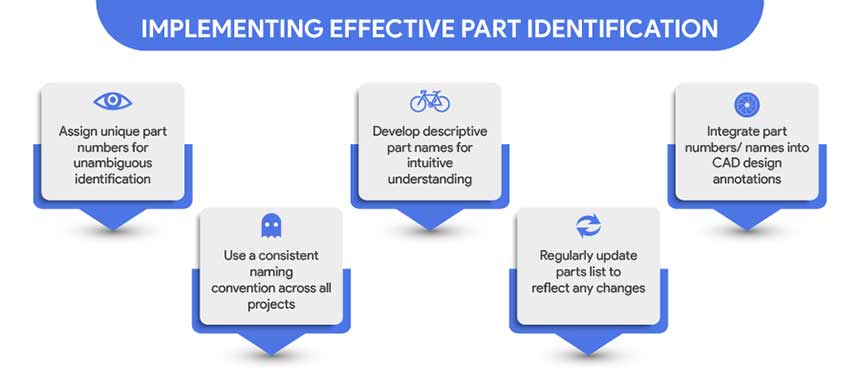
Tip 1: Implement Effective Part Identification
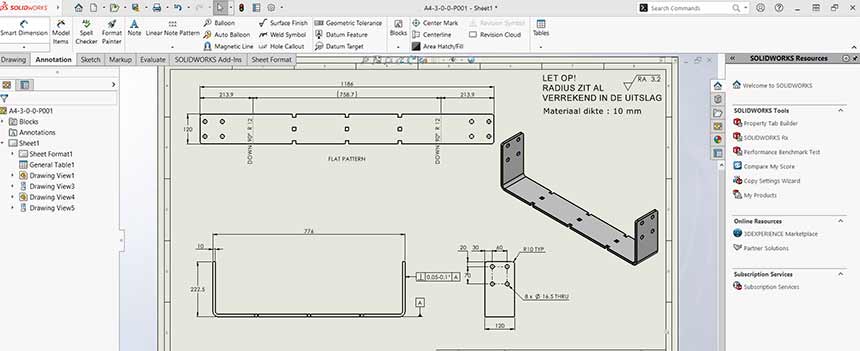
Begin by assigning unique part numbers or codes to each component, which will simplify the tracking of parts through the manufacturing process.
MAKE PART IDENTIFICATION AND TRACKING EASY WITH CAD
When dealing with multiple revisions or variants, implement barcode or QR code tagging on your parts to streamline assembly and quality control processes. These can be easily integrated into your CAD models and then on the physical parts. Also, leverage metadata within your CAD software to embed relevant information such as material specifications, thickness, and bend radius directly into your models. This ensures that all necessary data travels with the part throughout the production cycle. For assemblies, consider creating a bill of materials (BOM) that automatically updates as changes are made to the model.
Utilize a logical and hierarchical numbering system that aligns with your overall parts library or inventory management system. Assigning unique part numbers alongside descriptive names to every piece of your project can drastically reduce the chances of component mix-ups.
This dual-identification system creates a clear reference, allowing fabricators to cross-verify parts against project plans quickly. It is indispensable for inventory management and version control.
In short:
When drafting, include a dedicated table that correlates part numbers with their corresponding names and descriptions.
Ensure that both identifiers are prominently displayed next to the part in question on the drafting sheets and the models themselves. This can be achieved by adding a text note or a leader line that points to the part, and should reflect the part’s function, material, and any other critical attributes.
For assemblies, consider creating a table like the following:
| Part Number | Part Name | Description | Material | Quantity |
|---|---|---|---|---|
| Part Number SM-AL-001 | Part Name Support Flange | Description Flat, 2mm flange | Material Aluminum | Quantity 35 |
| Part Number SM-ST-002 | Part Name Mounting Bracket | Description 90-degree, 3mm bracket | Material Steel | Quantity 16 |
Additionally, it is essential to include a bill of materials (BOM) on the drafting sheet or within the modeling software, which lists all parts, their identifiers, and necessary quantities. This BOM will serve as a cross-reference that can be invaluable during assembly or when ordering replacements.
Incorporate metadata within your CAD files and CAD software’s parts library to further enhance part identification and streamline the process.
This metadata can include the part number, description, material specifications, and any relevant notes. By setting up a database that links part numbers with their names, you can employ automated tools to populate the drafting sheets, which further mitigates human error.
When updating the parts library, follow a consistent naming convention that includes material type, thickness, and all other relevant attributes, ensuring that each part is easily identifiable at a glance.
This practice not only enhances workflow efficiency but also facilitates better communication among team members, as everyone will be referencing the same clearly defined parts list.
Tip 2: Specify Parts with Precision
When working with sheet metal, precise hardware specifications are crucial for ensuring a perfect fit and function. To achieve this, utilize CAD software with sheet metal-specific features that allow you to input detailed hardware data such as fastener types, sizes, and locations. For this, many prefer to convert solid parts to sheet metal parts in SolidWorks using sheet metal specific tools.
Implement a standardized parts library within your CAD environment. Integration parts libraries, such as SolidWorks or AutoCAD can provide you with a comprehensive database of standard parts. By using these libraries, you can drag and drop pre-modeled parts into your design, ensuring consistency and precision.
For custom hardware not found in libraries, create detailed models that reflect the exact dimensions and tolerances required. When detailing these components, it is essential to consider how the hardware interacts with the sheet metal. This includes accounting for clearances, threading, and the material’s ability to sustain the hardware’s stress. For repeatable accuracy, create a checklist that includes:
- Material compatibility
- Required clearances
- Thread specifications
- Load-bearing capacities
When drafting, you should also apply proper clearances and tolerances for hardware insertion, which can be predetermined for specific hardware types in your library.
For complex assemblies, consider creating a custom table that lists all the hardware specifications, which can be embedded directly into the model space or accompanying documentation to ensure all team members have access to this crucial information.
| Hardware Type | Size | Clearance | Tolerance |
|---|---|---|---|
| Hardware Type Rivets | Size 3 mm | Clearance 0.5 mm | Tolerance ±0.1 mm |
| Hardware Type Screws | Size M4 | Clearance 0.5 mm | Tolerance ±0.1 mm |
| Hardware Type Nuts | Size M4 | Clearance 0.3 mm | Tolerance ±0.05 mm |
Adopting these techniques will lead to more accurate and efficient sheet metal drafting and modeling, reducing revisions and errors during the manufacturing process. Also, clear labeling helps with efficient part sourcing and maintains the design integrity in the final product.
Always cross-reference the hardware with the actual model and the material specifications to avoid costly mistakes.
Guidance on specifying parts to streamline the sourcing process
When detailing your designs, it is imperative to include exact hardware names and manufacturers. Incorporating specific hardware components such as PEM nuts or Southco latches by name and manufacturer into sheet metal designs ensures precise specifications and streamlines the sourcing process.
This not only streamlines the procurement process but also reduces the likelihood of incompatible or incorrect hardware being sourced. To achieve this, follow a structured approach:
- Utilize a comprehensive hardware library within your CAD software that includes standardized parts from reputable manufacturers.
- When specifying hardware such as fasteners, hinges, or brackets, and always include the manufacturer’s part number alongside the generic description. This ensures that the exact item can be sourced without ambiguity.
- For custom components, provide detailed drawings and specifications that can be used to fabricate or source the item accurately.
- Implement a version control system for your hardware library to keep track of any changes or updates to the parts used in your designs.
- Collaborate with suppliers to understand their catalog offerings and use this knowledge to standardize hardware selections across multiple designs, where feasible.
Consider this example table for specifying fasteners in a design:
| Component ID | Description | Manufacturer | Part Number | Material | Quantity |
|---|---|---|---|---|---|
| Component ID SMF-001 | Description M4 x 10mm Hex Bolt | Manufacturer Fastenal | Part Number B1234 | Material Stainless Steel | Quantity 8 |
| Component ID SMF-002 | Description M5 x 12mm Countersunk Screw | Manufacturer McMaster-Carr | Part Number 91251A537 | Material Aluminum | Quantity 16 |
It is essential to provide clear specifications to avoid any confusion during the sourcing process. Use the following methods to ensure precision in your hardware specifications for sourcing:
- Material Specifications: Clearly define the type of material required for each hardware component, including grade, finish, and any treatment needed. This could include specifying stainless steel vs. galvanized steel or coated vs. uncoated surfaces.
- Size and Dimensions: Provide exact measurements for each piece of hardware. Use calipers or other precise measuring tools to capture dimensions accurately and include tolerances to ensure proper fit.
- Thread Details: For threaded components, specify the thread size, type (such as metric or imperial), and count (threads per inch). This is crucial for the compatibility of nuts, bolts, and screws.
- Strength Requirements: Indicate the load requirements for the hardware, including tensile strength and shear strength, to ensure the hardware can withstand the forces applied during use.
- Standards Compliance: Reference any industry standards or certifications that the hardware must meet, such as ISO or ASTM standards, to ensure quality and interoperability.
- Quantity: State the precise number of each hardware component required, considering any potential need for spares.
- Part Numbers: If possible, provide the manufacturer’s part numbers to streamline the ordering process and eliminate any guesswork.
- Supplier Information: Include preferred suppliers or distributors to expedite the sourcing process, especially for specialized or custom hardware.
- Attachment Methods: Specify the required methods for attaching the hardware to the sheet metal, such as welding, riveting, or adhesive bonding.
- Assembly Instructions: Provide clear assembly instructions or diagrams to ensure that the hardware is installed correctly and functions as intended.
By adhering to these guidelines, you can significantly reduce the risk of project delays caused by hardware sourcing issues and ensure that your sheet metal components are assembled seamlessly and efficiently.
Tips to avoid misunderstandings and ensure the use of correct components
To mitigate confusion and guarantee the integration of the appropriate components, it is critical to specify hardware in sheet metal designs with utmost precision. Adhering to best practices for sheet metal fabrication, one must meticulously define dimensions, tolerances, and material specifications, including mechanical properties and desired finishes.
Consistency in documenting bend radius, offsets, and other structural features prevents discrepancies during fabrication processes. By incorporating Design for Manufacturability principles, designers ensure that the theoretical resilience and practical application align, thereby upholding the integrity of the final product.
In order to avoid misunderstandings and ensure the correct use of components in sheet metal drafting and modeling, adhere to the following techniques:
- Utilize clear labeling and standardized part numbers for each component within your drafts to minimize confusion.
- Implement a color-coding system to distinguish between different materials or thicknesses, which can be easily referenced in a legend.
- Always double-check your work against the original specifications and design requirements to confirm that you’re using the correct components.
- Create a peer review process where another team member verifies the components and their specifications in your model.
- Leverage version control mechanisms to track changes and ensure that the most current component information is being used.
- Make sure to use up-to-date libraries and databases for your components to prevent the use of outdated or incorrect parts.
- Establish a checklist for common components and materials used in your projects to ensure consistency across different models and drafts.
When possible, integrate automated validation tools within your CAD software to check for common errors or inconsistencies. Establish a centralized database of components that is regularly updated, providing a single source of truth for all team members.
Include tolerance information directly in the model to ensure that all components fit together as intended. Provide assembly instructions or exploded views within the drafting documentation to guide the correct assembly of components. Lastly, maintain open communication channels with fabricators to receive feedback and make necessary adjustments to the model or drafting techniques.
By systematically implementing these practices, the risk of using incorrect components can be greatly reduced, leading to a more efficient and error-free design process.
Tip 3: Adopt Rigorous Revision Control
Maintaining a stringent revision control system is essential in sheet metal drafting and modeling to ensure that the most current and accurate designs are being used.
Utilize a version control software that tracks changes, manages file versions, and allows for the recovery of previous versions if necessary.
This is vital for avoiding costly mistakes, such as manufacturing the wrong version of a part or wasting engineering time tracking changes. Poor revision control can lead to significant financial losses and delays.
Every time a draft is modified, it should be saved as a new version, with a clear naming convention that includes the version number, date, and a brief description of the changes.
For instance, “Bracket_v2.3_032423_ExtendedFlange” clearly indicates the iteration and the nature of the revision. This practice allows for easy tracking of the evolution of your design and simplifies the process of reverting to previous versions if necessary.
| Version | Date | Description | Editor |
|---|---|---|---|
| Version 1.0 | Date 03/01/23 | Description Initial draft | Editor Jane Doe |
| Version 1.1 | Date 03/05/23 | Description Added reinforcement ribs | Editor John Smith |
| Version 2.0 | Date 03/12/23 | Description Redesigned for material efficiency | Editor Jane Doe |
It is also critical to document the reasoning behind each revision in a change log, which can be maintained as a simple table with columns for version number, date, description, and the name of the person who made the changes. This log should be easily accessible to all team members.
Conduct periodic audits of your revision control process to ensure compliance and to identify areas for improvement.
Adopt a check-in/check-out system to prevent simultaneous edits that could lead to conflicts or data loss. These steps will significantly reduce errors and save time in the long run, leading to a more efficient and streamlined drafting process.
Best practices for meticulous documentation of revisions
Any revision, whether minor wording adjustments or significant geometry changes, should be thoroughly documented.
Revision notes can be placed in various sections of a print, such as the title block or the revision block, and it’s crucial that the information is consistent across all locations. This minimizes confusion and ensures that fabrication shops don’t overlook critical change.
Effective revision control will always include a comprehensive revision table. This table records all changes, including reasons, dates, and approvals. Human error is the greatest risk, so ensuring changes are properly documented is key to an accurate and cost-efficient manufacturing process.
Understanding versions and revisions
It’s important to distinguish between ‘versions’ and ‘revisions’ in CAD files. Versions generally refer to updates in the file, often tracked automatically by CAD data management systems. Revisions, however, are more significant and denote milestones in the design process, such as readiness for manufacturing. These are usually designated manually, such as by adding a suffix to the part number (e.g., “Rev A”). Revisions communicate crucial information about the design’s stage and are particularly important for manufacturing.
Adopting strict documentation practices is essential for achieving freedom in design variation and continuous improvement.
To sum up:
- Utilize advanced CAD software to track changes and automatically update documentation.
- Establish standardized naming conventions for clarity and ease of identification.
- Designate revisions properly by adding a suffix to the part number.
- Embed detailed revision logs directly within the design files to maintain a coherent history.
- Use CAD’s renaming feature to ensure parametric links are updated in related files.
- Perform regular audits on revision records to verify accuracy and completeness.
- Train all team members on the importance of thorough documentation to foster collective responsibility.
Incorporate automated backup systems to safeguard against data loss, ensuring that all revisions are preserved. Finally, provide clear communication channels among team members to discuss and clarify any changes, promoting a collaborative environment for continuous improvement.
Selecting the right system for revision control
Selecting a process for version and revision management depends on your specific needs. What works for a large corporation might not suit a smaller firm.
Smaller teams may handle versions and revisions manually, adding revision numbers to part numbers or file names. Medium-sized teams might use cloud-based PDM (Product Data Management) tools like GrabCAD Workbench, which offer a balance between control and simplicity.
Larger organizations typically invest in fully automated revision control with traditional PLM (Product Lifecycle Management) or PDM systems. These systems offer sophisticated control over versions and revisions, integrating with other business systems like ERP (Enterprise Resource Planning).
The key is to assess your requirements based on the complexity of your design and release processes, the size of your team, and the extent of collaboration with external partners or suppliers.
Tip 4: Consider Grain Direction in Design
Understanding the grain direction is crucial when drafting and modeling sheet metal components. The grain refers to the alignment of the metal’s crystalline structure, which can significantly affect its strength and flexibility.
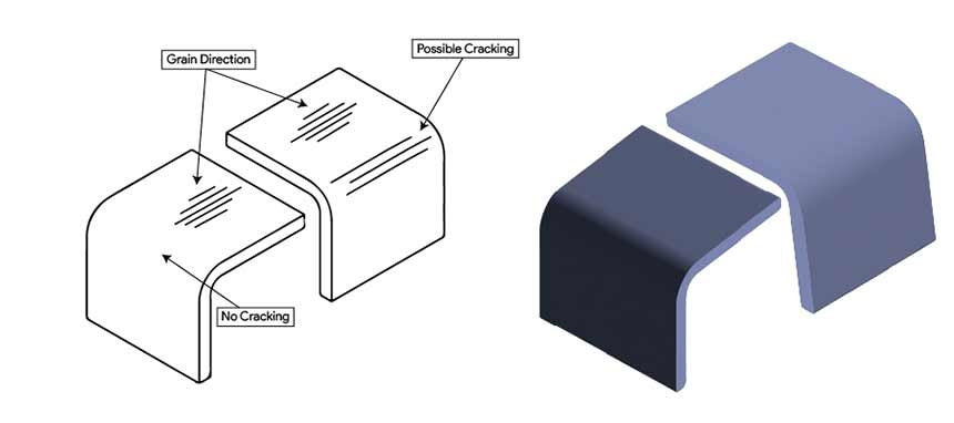
It’s crucial to account for the material’s grain when designing parts that will undergo bending or other forms of stress. Grain direction should run parallel or perpendicular to bends according to needs to minimize the risk of cracking and to maximize the structural integrity of the part.
To ensure proper grain orientation, follow these steps:
- Always consider the grain direction when laying out parts on a sheet, as it impacts the metal’s bending and forming characteristics.
- Identify the grain direction on the provided material stock, which is often indicated by the rolling direction or by markings from the supplier.
- Apply the grain direction in your CAD software as an annotation or layer, making it a constant reference throughout the design process.
- Use software tools to visualize grain direction during the CAD phase, helping to predict how the metal will behave during fabrication.
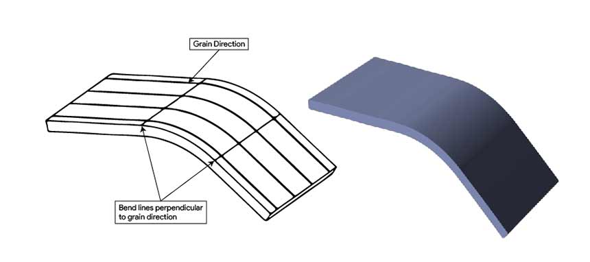
- When designing bends, ensure they are perpendicular to the grain to increase part strength and avoid cracking.
- In cases where bends must be parallel to the grain to reduce stiffness, increase the bend radius to reduce the risk of damage.
- Optimize nesting patterns to align the grain direction with the principal stress lines of the final part to enhance durability.
- When creating the flat pattern, adjust the bend deduction values, if necessary, as they can vary with the grain orientation.
- Communicate clearly with the fabrication team; include detailed notes or diagrams on the drawings to indicate the desired grain direction for each part.
By integrating these techniques into your workflow, you can improve the structural integrity and longevity of your sheet metal designs. Remember, the grain direction can be as influential as the material choice itself.
Here’s an example of how to denote grain direction in a simple table format, suitable for inclusion in technical documentation:
| Part Number | Description | Grain Direction |
|---|---|---|
| Part Number Top Cover | Description Top Cover | Grain Direction Parallel to longest edge |
| Part Number 1002-B | Description Side Panel | Grain Direction Perpendicular to front edge |
Strategically accounting for grain orientation during the drafting phase can significantly reinforce structural integrity, particularly in areas subjected to bending or forming processes. Also, aligning design elements with the grain direction optimizes material usage and enhances the visual appeal of metal surfaces, making it a critical consideration for precision engineering.
Importance of grain direction in design specifications
In sheet metal drafting and modeling work, you need to keep in mind that the grain direction of the metal influences how the material will react to certain manufacturing processes, particularly bending and finishing.
- Bending: Metal is more ductile and bends more easily along the grain. When creating bends, align them parallel to the grain to reduce the risk of cracking or breaking. For optimal strength in bends, the grain should run perpendicular to the bend axis.
- Cutting: Design your parts so that cuts are primarily along the grain. This practice can reduce wear on cutting tools and improve the cut quality.
- Finishing: Surface finishes will appear consistent when applied along the grain direction. When the grain is not considered, finishes may look uneven or may wear unpredictably over time.
Here is a simple table to include in your design specifications to help communicate these details:
| Feature | Grain Direction | Notes |
|---|---|---|
| Feature Bend #1 | Grain Direction Parallel | Notes Grain direction ensures ductility during bending. |
| Feature Cut #1 | Grain Direction Along | Notes Reduces tool wear and improves edge quality. |
| Feature Finish | Grain Direction Along | Notes Ensures consistent surface appearance. |
Understanding and respecting the grain direction is crucial for fabricators as it can significantly impact the strength, flexibility, and finish of the final product. Here are techniques to ensure proper grain consideration in your sheet metal drafting and modeling:
- Align bends with the grain direction to reduce the risk of cracking.
- Orient the grain to support the primary load direction for enhanced strength.
- Factor grain direction into your design to anticipate and compensate for material springback.
- Design flanges and critical features parallel to the grain to maintain consistent mechanical properties.
- Communicate grain direction clearly in specifications to ensure proper fabrication.
Adhering to these principles affords the freedom to leverage the material’s innate qualities, yielding superior and reliable sheet metal parts.
How grain direction impacts aesthetics and structural integrity
During the drafting and modeling phase, always consider the grain direction for the following reasons:
- Strength and Flexibility: Metal has varying strength along different axes. Aligning the grain direction with the primary axis of stress can enhance the product’s durability. For bends, position them perpendicular to the grain to reduce the risk of cracking.
- Visual Appeal: The grain can affect the finish of the metal. For visible components, ensure the grain direction is consistent to achieve a uniform appearance.
- Dimensional Accuracy: When metal is bent, the grain direction can influence the amount of spring-back. Account for this in your design to maintain precision.
Use software features that allow you to specify grain constraints and ensure that your flat pattern layouts are optimized accordingly. Always double-check your work with a Design for Manufacturability (DFM) checklist that includes grain direction considerations. Here’s a simple table to summarize key points:
| Aspect | Technique | Consideration |
|---|---|---|
| Aspect Strength | Technique Grain Alignment | Consideration Align with stress axis |
| Aspect Flexibility | Technique Bend Orientation | Consideration Perpendicular to grain |
| Aspect Visual | Technique Consistent Direction | Consideration Uniform finish |
| Aspect Accuracy | Technique Spring-back Compensation | Consideration Adjust for grain impact |
In terms of structural integrity, aligning structural elements such as flanges or tabs with the grain direction enhance their strength. For critical components, you need to balance the material utilization with the grain direction to achieve both the desired strength and material efficiency.
To ensure optimal aesthetics, consider the grain direction in relation to the visible surfaces. For brushed or patterned metals, the grain should be consistent and should follow the shape’s main axis to achieve a uniform appearance.
Use the following table as a quick reference for how grain direction affects different aspects of your sheet metal parts:
| Aspect | Impact of Grain Direction |
|---|---|
| Aspect Bending | Impact of Grain Direction Better ductility and reduced risk of cracking when bend is parallel to the grain |
| Aspect Aesthetics | Impact of Grain Direction Uniform appearance when grain follows the main axis of visible surfaces |
| Aspect Structural Integrity | Impact of Grain Direction Enhanced strength when structural elements are aligned with the grain |
Incorporate checks for grain direction early in your design process to avoid costly rework or structural failures. By accounting for grain direction, you can produce sheet metal parts that are not only visually appealing but also meet all necessary structural requirements.
Tip 5: Define Powder Coating Specifications Clearly
When detailing powder coating specifications in your sheet metal drafts, precision is crucial to ensure the final product meets the desired quality and finish.
It is essential to incorporate comprehensive details such as the type of powder coat, color, texture, thickness, and gloss level. Specify the pre-treatment process to be used, which could include cleaning, etching, or phosphating, as this will affect the coating’s adhesion and longevity.
Adhere to the correct material thickness: powder coating adds a layer that can affect the final dimensions. Use proper edge profiling to enable the powder to adhere evenly, avoiding sharp edges that could lead to uneven coating. It’s essential to incorporate appropriate flanges and bends in your design to compensate for the powder coating’s thickness, which can affect how parts fit together.
The coating thickness should be clearly stated, typically ranging from 2 to 10 mils (50 to 250 micrometers) and can be critical for both aesthetic and functional performance.
The curing schedule, which includes the temperature and time at which the powder should be cured, must be defined to ensure proper bonding and durability.
Allow for adequate drainage holes in your design to prevent powder accumulation during the coating process.
Design with assembly in mind, considering how the powder coating will interact with other components. Utilize relief cuts to mitigate warping caused by the high temperatures used in the powder coating process.
Ensure that you specify the type of powder coating in your design documentation to inform the coaters of the exact requirements. Always check for industry standards regarding powder coating thickness and application to maintain quality and durability.
Additionally, it is important to note whether the part requires a single coat or multiple coats, and if a clear topcoat is necessary for added protection.
For complex parts, include a detailed diagram indicating areas with different specifications or those that should be masked prior to coating to avoid interference with part functionality. Utilize tables to succinctly present the data, such as:
| Area | Coating Type | Thickness | Color Code | Texture |
|---|---|---|---|---|
| Area Exterior | Coating Type Epoxy | Thickness 3 mils | Color Code RAL 9003 | Texture Smooth |
| Area Interior | Coating Type Polyurethane | Thickness 5 mils | Color Code RAL 7016 | Texture Matte |
Ensure that the specifications align with industry standards such as ASTM or ISO to facilitate communication with fabricators and maintain consistency in production. Clearly defined powder coating specifications in your sheet metal models will help reduce ambiguity, minimize errors, and save time during the manufacturing process.
Detailed instructions on powder coating processes
Begin by designing components with uniform wall thicknesses to avoid warping during the curing phase. Ensure that all corners are rounded to a minimum radius that complies with the powder coating specifications, as sharp angles can lead to uneven coating.
It is also important to avoid deep recesses in your design; powder coating may not penetrate these areas, resulting in incomplete coverage.
When detailing your drawings, specify proper masking areas to protect critical dimensions and features from the coating. Moreover, include tolerances that account for the thickness of the powder coating, which typically ranges from 2 to 4 mils.
For holes and threaded features, it is recommended to design them slightly larger to accommodate the coating thickness, or plan for post-coating tapping. Use a dedicated layer in your CAD software for elements related to the powder coating process to streamline communication with the manufacturer.
Here is an example of a table providing a quick reference for drafting considerations specific to powder coating:
| Feature | Design Consideration | Typical Value |
|---|---|---|
| Feature Wall Thickness | Design Consideration Uniformity | Typical Value As per material spec |
| Feature Corners | Design Consideration Minimum Radius | Typical Value 3mm |
| Feature Recesses | Design Consideration Avoid Deep Designs | Typical Value N/A |
| Feature Masking Areas | Design Consideration Specify in Drawing | Typical Value As per critical features |
| Feature Tolerances | Design Consideration Include Coating Thickness | Typical Value 2-4 mils |
| Feature Holes/Threads | Design Consideration Adjust for Coating | Typical Value Diameter +0.1mm |
Key specifications and considerations:
Finish Classes: Powder coat paint specifications are commonly categorized into three classes based on cost, aesthetics, defect allowance, and inspection time:
- Class A Finish: High cost, minimal defects, longer inspection, used where high aesthetics are vital.
- Class B Finish: Medium cost, few defects, average inspection, used for parts visible to the customer.
- Class C Finish: Lower cost, more defects, used on hidden parts where corrosion protection is important, but cosmetic blemishes are not.
Thickness Addition: Powder coating typically adds about 0.002″ to 0.004″ to each surface of a part, impacting both function and appearance. This addition needs to be accounted for in the design phase.
Hanging Requirements for Coating:
- Existing Holes: Utilizing existing holes for hanging parts during powder coating.
- New Holes: Designing a 0.125” diameter hole in an inconspicuous area for hanging.
- Break-off Tabs or Clips: Used when permanent holes are not feasible; these may require final touch-up, increasing costs.
Accounting for Buildup: Powder coating results in a buildup of approximately 0.003”-0.004”, which should be factored into designs, especially those with tight hole tolerances.
Specific Colors, Textures, and Sheens: Specify exact RAL (color code), texture, and gloss for a specific brand to ensure the final appearance matches expectations. Color consistency from prototype to production is important, and availability and cost of powder coat types should be compared.
Pre-Treatments: For enhanced corrosion resistance or electrical conductivity, treatments like chromate or zinc can be requested before powder coating.
Hardware Insertion: Certain types of hardware should be added after powder coating to ensure proper functionality. This consideration is vital for components like panel fasteners and quarter-turn hardware.
Color Selection: Opting for a single color is advisable as applying multiple colors can be challenging, risky, and costly. For multi-colored parts, wet paint is a better option.
Before finalizing the design, consult with your powder coating supplier to ensure that all aspects of the design are feasible and that the chosen materials are compatible with their process. This collaboration can help prevent costly rework and ensure a high-quality finish on the final product.
Always validate your design against industry standards and best practices for powder coating to ensure optimal results.
Tip 6: Optimize with SolidWorks Sheet Metal Module
When trying to create effective SolidWorks CAD models of sheet metal designs, begin by setting up your material parameters correctly, including thickness, bend radius, and K-factor, as these will affect the accuracy of your flat patterns and bend deductions.
Utilize the Base Flange/Tab feature to create your primary sheet metal part, and then add flanges and other features with the Edge Flange tool. This ensures that all bends are accounted for and that the part can be manufactured without issues.
For complex bends or unique geometry, use the Sketched Bend or Miter Flange tools to achieve the desired shape.
To avoid errors in the design phase, always check the flat pattern to ensure there are no overlapping edges or impossible bends. The “Convert to Sheet Metal” feature can be useful for turning solid parts into sheet metal components, but make sure to inspect and adjust the conversion for manufacturability.
When you need to make cuts or holes in the sheet metal, use the Normal Cut option to ensure the cut is normal to the surface, regardless of the bend state. This prevents distortion during the manufacturing process. Lastly, use the Fold/Unfold features to flatten complex parts for easier feature addition, and then refold them to ensure the features align correctly in the 3D model.
For a more efficient workflow, consider customizing your toolbar to have quick access to the most frequently used sheet metal tools. Additionally, create and save your own custom bend tables for consistent application across all your sheet metal projects.
Here is a simple example of how you might organize your custom bend tables using WordPress table classes:
| Bend Angle | Bend Radius | K-Factor |
|---|---|---|
| Bend Angle 90° | Bend Radius 0.5mm | K-Factor 0.4 |
| Bend Angle 45° | Bend Radius 0.5mm | K-Factor 0.4 |
| Bend Angle 30° | Bend Radius 0.5mm | K-Factor 0.4 |
Remember to always validate your designs using the “Sheet Metal Gauge Table” and the “Sheet Metal Costing Tool” within SolidWorks to predict the cost and feasibility of manufacturing your part. These proactive steps help in identifying potential issues before they become costly mistakes during production.
Leverage the SolidWorks Sheet Metal Module for enhanced design accuracy
Always start by setting the correct material properties and sheet metal thickness to ensure that your design reflects the real-world application. In SolidWorks, you can easily define and edit these parameters under the Sheet Metal Gauges settings.
Next, make use of the K-Factor or Bend Allowance to accurately predict the bending process, which is crucial for precise fitting parts. The K-Factor, which defines the ratio of the neutral axis’ position, can be adjusted within the Sheet Metal Parameters.
For complex bends, the Sketched Bend feature allows for the creation of unique bend profiles. Ensure to use the Flatten feature to check for interferences and manufacturability before the final production. Additionally, the Convert to Sheet Metal option is a powerful tool for turning solid parts into sheet metal components, which is especially useful when working with imported geometry or designs initially created as solids.
When designing in-context of assemblies, make sure to use the Insert Bends or the Rip features to accurately account for the assembly constraints. To optimize the design process, create and utilize custom sheet metal form tools for frequently used features. This can be done by designing a form tool part and then saving it into the Design Library for future use.
Finally, always validate your design using the SolidWorks Simulation feature to test for strength and durability under real-life conditions. This step is critical to avoid costly manufacturing errors and to ensure that your design can withstand the stresses of its intended use.
Below is a simple example of a table to compare two different methods for creating a sheet metal part in SolidWorks:
| Feature | Base Flange/Tab Method | Convert to Sheet Metal Method |
|---|---|---|
| Feature Starting Point | Base Flange/Tab Method 2D Sketch | Convert to Sheet Metal Method 3D Solid Part |
| Feature Design Intent | Base Flange/Tab Method Specific for Sheet Metal | Convert to Sheet Metal Method Adaptation of Existing Design |
| Feature Complexity | Base Flange/Tab Method Suitable for Simple Designs | Convert to Sheet Metal Method Suitable for Complex Geometries |
| Feature Customization | Base Flange/Tab Method Limited by Sketch | Convert to Sheet Metal Method Highly Customizable |
To sum up:
- Utilize the K-Factor: Adjust the K-factor parameter to reflect the specific material and bending method, ensuring accurate bend allowance calculations.
- Sketch Bend Lines: Directly sketching bend lines on the flat pattern can provide better control over the bend locations, leading to precise outcomes.
- Set Proper Relief Cuts: Configure corner reliefs to prevent material overlap, which can cause issues during the fabrication process.
- Leverage the Flatten Feature: Regularly use the ‘Flatten’ feature to check for interferences or overlaps in the flat state, avoiding manufacturing errors.
- Use Forming Tools: Incorporate forming tools from the SolidWorks library to accurately represent complex features like louvers or ribs.
- Validate with Simulation: Run simulations to predict material behavior and potential issues, such as stress or deformation, before production.
- Optimize Nesting: Use the nesting capabilities to optimize material usage and minimize waste.
- Create Configurations for Different Stages: Set up multiple configurations to represent the part at various stages of production for clearer communication with the shop floor.
- Employ Custom Properties: Input material specifications and other relevant data into custom properties for automated BOM generation.
- Maintain Consistent Sheet Metal Gauges: Standardize sheet metal gauge across parts to ensure uniformity and reduce potential errors during assembly.
By incorporating these techniques into your workflow, you can leverage the full potential of the SolidWorks Sheet Metal Module to create accurate and manufacturable sheet metal designs. Always remember to refer to SolidWorks tutorials and guidelines for more detailed instructions.
Tip 7: Explore SolidWorks Weldments for Structural Design
By leveraging the Weldments feature in SolidWorks, you can create complex structures using standard profiles and avoid the need to model each member individually.
Utilize this module to:
- Streamline the creation of 3D structures: By using the weldment profiles, you can quickly assemble complex structures without needing to model each member individually.
- Automate cut lists and bills of materials: The module generates these elements automatically, saving time and reducing the potential for human error.
- Ensure consistency in design: Predefined profiles ensure that standard sizes and shapes are used, maintaining design uniformity across projects.
- Simplify the modification process: Changes to the primary sketch or profile propagate throughout the entire structure, making alterations straightforward and less time-consuming.
- Facilitate the creation of 2D documentation: Automatically generate flat patterns and detailed drawings with all necessary annotations and dimensions.
- Optimize material usage: The module helps in minimizing waste by efficiently planning the layout of weldment cuts.
- Enhance collaboration: Share standardized profiles among team members to ensure that everyone is working with the same parameters.
- Improve accuracy: Use the built-in tools for checking interferences and clearances to reduce the risk of errors during the fabrication process.
By incorporating these techniques, you can leverage the full potential of SolidWorks Weldments for more efficient and accurate sheet metal drafting and modeling.
Utilizing the weldments module for assemblies requiring welding
Optimize your workflow by first sketching the basic structure of your weldment assembly, using lines and arcs to represent the path of the weldments. Then, apply structural member profiles to these paths, which can be standard shapes like angles, channels, and tubes, or custom profiles if your project demands it.
It’s crucial to configure the corner treatments properly to ensure that members intersect correctly, which will save you time and material during the actual welding process.
To fully leverage this feature:
- Predefine Weldment Profiles: Ensure you have a library of standard weldment profiles that are commonly used in your industry. This will save time and maintain consistency across your designs.
- Use 3D Sketching for Path Definition: Create a 3D sketch to define the path where structural members need to be placed. This will help in visualizing the assembly and identifying potential issues early in the design process.
- Trim/Extend Feature: Utilize the trim/extend feature to adjust the length of the members precisely, ensuring they fit together correctly with minimal adjustments needed during the actual welding process.
- Corner Treatments: Apply appropriate corner treatments to your weldment parts to simulate real-world welding conditions. This will give a more accurate representation of the finished product and help in creating more detailed drawings.
- Weldment Cut List: Automatically generate a cut list that can be used for fabrication. This list includes all the necessary information such as the description, length, angle cuts, and quantity of each item.
- Use Configuration: Manage different versions of the weldment within the same part file using configurations. This can be particularly useful when creating variations of the same assembly that require different weldment profiles or lengths.
- Weld Beads: Add weld beads to your assembly model to visually represent where welds will be applied. While they are typically not used for manufacturing, they can be beneficial for creating more complete drawings and for communication with the welding team.
- Sheet Metal Features: Integrate the use of sheet metal features such as bends, flanges, and reliefs into your weldments where necessary to create complex fabrications.
- Material Properties: Assign accurate material properties to your weldment profiles for correct mass calculations and to ensure that the center of gravity is properly represented.
- Post-Weld Operations: Consider any post-weld operations such as machining or finishing processes and reflect these in your model accordingly to ensure they are accounted for in the final design.
For assemblies with repetitive elements, make use of configurations to represent different versions without the need to create multiple separate models. This keeps your project organized and reduces file size, even when you are focused on detailed engineering design.
Finally, always generate detailed drawings from your weldment model, including standard views, cut lists, and itemized bills of material. These drawings should clearly indicate weld symbols, types, and sizes in accordance with relevant welding standards, ensuring that the manufacturing team has all the information they need for production.
Simplifying complex structural designs with this specialized tool
Begin by setting up your parameters; these could be dimensions, material properties, or bend allowances that are specific to your project. Next, use the software’s built-in features to generate complex shapes and patterns, which can be a challenge when done manually.
Techniques such as mirroring, patterning, and the use of configurable design tables can expedite the design process. For instance, if you’re working on a perforated panel, instead of drafting each hole individually, create one hole and use the pattern feature to duplicate it across the panel accurately and efficiently.
To simplify complex designs:
- Utilize Parametric Design: By defining relationships between different design elements, you can ensure that changes to one feature will automatically update related features, maintaining the integrity of your design.
- Apply Sheet Metal Specific Features: Take advantage of specialized sheet metal features like flange, lofted bend, and hem tools. These are designed to mimic real-world manufacturing processes and provide accurate visualizations of the final product.
- Standardize Material Thickness: Consistency in material thickness simplifies the manufacturing process. Use a predefined list of standard gauges to avoid unnecessary complexity and ensure compatibility with your manufacturing capabilities.
- Implement Design for Manufacturability (DFM): Integrate DFM principles by considering factors like bend radii, minimum flange lengths, and hole spacing during the design phase. This approach minimizes the need for costly revisions and rework.
- Use Sheet Metal Unfold Tools: Employ software features that can unfold complex parts into flat patterns. This not only facilitates accurate drafting but also provides a clear blueprint for the cutting and bending stages.
- Optimize Nesting: Enhance material utilization by using nesting techniques that arrange parts efficiently on a sheet. Software with nesting capabilities can significantly reduce material waste and production time.
- Leverage Libraries and Templates: Save time by creating and using libraries of common features and templates for frequently used components. This promotes standardization and accelerates the design process.
- Incorporate Corner Treatments: Account for corner treatments like reliefs and notches in your designs to prevent material overlap and facilitate the bending process.
- Conduct Simulations: Run simulations to test your designs under virtual conditions. This can help identify potential issues like material stress and deformation before the manufacturing stage.
- Maintain Detailed Documentation: Keep detailed records of your design specifications, including bend deductions and K-factors. Accurate documentation ensures that the manufacturing team has all the necessary information to produce the part correctly.
| Material Thickness | K-Factor |
|---|---|
| Material Thickness 0.5 mm | K-Factor 0.4 |
| Material Thickness 1.0 mm | K-Factor 0.44 |
| Material Thickness 2.0 mm | K-Factor 0.5 |
When dealing with bends, employ the tool’s bend deduction calculations to ensure precision in the final product. It’s crucial to input the correct material thickness, bend radius, and K-factor into the software to achieve accurate flat patterns. Moreover, make use of the software’s ability to simulate the bending process to foresee any potential issues such as material collision or improper bend sequences.
Tip 8: Standardize Bend Radii for Efficiency
When drafting and modeling sheet metal, consistency in bend radii not only streamlines the manufacturing process but also reduces tooling costs, material fatigue and setup times. To achieve this, establish a set of standard bend radii that are suitable for the material thickness and type being used.
Industry Standard Bend Radius
A commonly used standard bend radius is 0.030 inches. This measurement is used for material thicknesses up to 0.125 inches (⅛ inch), with an increase in bend radius for thicker materials. This standard ensures consistent, high-quality parts with solid structural integrity.
Start by consulting the material’s specifications to determine the minimum radius that will not cause cracking or excessive strain. Once you have this information, you can create a standardized table of bend radii for your organization.
| Material Thickness | Minimum Bend Radius | Standard Bend Radius |
|---|---|---|
| Material Thickness 0.5 mm | Minimum Bend Radius 0.8 mm | Standard Bend Radiuss 1 mm |
| Material Thickness 1 mm | Minimum Bend Radius 1.5 mm | Standard Bend Radiuss 2 mm |
| Material Thickness 2 mm | Minimum Bend Radius 3 mm | Standard Bend Radiuss 4 mm |
Incorporate these standard radii into your CAD software’s library or tooling database to ensure they are used consistently across all designs.
Material Thickness Proportionality
For some materials, the recommended inside bend radius for sheet metal parts should be equal to the material thickness. Specifically for harder materials like stainless steel and CRCA (cold rolled close annealed), an inside bend radius equal to 0.65 times the sheet thickness is sufficient.
Implement a software check in your CAD program to flag any deviations from the standard radius, ensuring that all bends adhere to the pre-defined parameters.
For critical components, create a reference table in your drafting documentation that lists the standard bend radius next to the material thickness, providing a quick cross-reference for the manufacturing team.
Standardizing bend radii helps to:
- Minimize Tooling Inventory: Reducing the variety of tools needed for different bend radii.
- Enhance Design Interchangeability: Facilitating the use of parts across multiple designs.
- Reduce Setup Time: Streamlining transitions between production runs.
- Improve Material Utilization: Decreasing waste by standardizing the bending process.
- Facilitate Quality Control: Simplifying inspection protocols with uniform standards.
Utilize parametric modeling practices to dynamically link the bend radius to the material thickness, ensuring that changes to the material automatically update the bend radius accordingly.
Minimum Recommended Ratio
A minimum recommended ratio for bending is 1:6 and bending with a ratio of less than 1:4 is generally not recommended. If strength permits, it is advisable to groove first and then bend to achieve a small sheet metal bending radius.
It’s also crucial that you align these standards with the capabilities of the bending machines in your manufacturing facility or those of your external vendors. This will ensure that your designs are not only efficient but also manufacturable.
By standardizing bend radii, you’ll improve the predictability of your sheet metal parts, leading to better fit during assembly and fewer revisions in the design-to-manufacture process.
Maintain consistent bend radii across different fabrication scenarios
Different materials and thicknesses require specific bend radii to avoid cracking or material deformation. To achieve consistency, start by selecting a standard bend radius that is suitable for most of the materials and thicknesses you work with. This standard can then be applied across all designs unless a particular material or design constraint dictates otherwise.
Use software tools that allow for the setting of default bend radii and ensure that these are adhered to during the drafting process. When exceptions are necessary, document the reasons and ensure that the fabrication team is aware of the special requirements.
Alternative Bend Radii Formula
In some cases, using a bend radius equal to the material thickness plus 0.031 inches may be acceptable. This approach, however, can be on the tighter side and might restrict the vendor from using standard tooling. For materials thinner than 0.031 inches, it is suggested not to use a bend radius less than 0.031 inches.
Implement a checklist to be used during the design review process that includes a verification of bend radii consistency. This will help to catch any deviations early on. Additionally, consider creating a table that lists preferred bend radii for various materials and thicknesses as a reference for designers.
Below is an example of such a table:
| Material | Thickness | Recommended Bend Radius |
|---|---|---|
| Material Aluminum | Thickness 0.8 mm | Recommended Bend Radius 1.6 mm |
| Material Steel | Thickness 1 mm | Recommended Bend Radius 2 mm |
| Material Stainless Steel | Thickness 1.2 mm | Recommended Bend Radius 2.4 mm |
In instances where the same part is to be fabricated using different methods or machines, it may be necessary to adjust the bend radius to accommodate the specific capabilities or limitations of the equipment.
However, these adjustments should be minimized to maintain process efficiency.
Tolerances in Designing
When designing parts with a standard bend radius, sheet metal tolerances are required to open. Some fabricators use a tolerance of +/- 0.010 inches for dimensions across a single bend. The bend radius itself is constrained to a tolerance of +/- 1.0.
For complex models, create a custom library of bend radii that can be quickly applied to new designs, ensuring that all team members use standardized values.
Moreover, document these standards in a design guide that accompanies the CAD files, to provide clear instructions for the fabrication team. When programming the CNC machines, use these predetermined radii to streamline the setup process.
Tip 9: Adhere to DFM/DFMA Principles
Design for Manufacturability and Assembly (DFM/DFMA) principles are crucial in sheet metal drafting and modeling. When adhering to these principles, focus on simplifying the design by reducing the number of parts and avoiding complex features that are difficult to fabricate.
Here’s an example of a simple table that could be included in a technical document, summarizing key DFM considerations for sheet metal drafting:
| DFM Principle | Consideration | Benefit |
|---|---|---|
| DFM Principle Material Selection | Consideration Use standard, readily available materials. | Benefit Reduces lead times and costs. |
| DFM Principle Design Simplicity | Consideration Maintain uniform wall thickness. | Benefit Simplifies fabrication and reduces waste. |
| DFM Principle Assembly Efficiency | Consideration Design self-locating and self-fastening parts. | Benefit Reduces assembly time and costs. |
For example, incorporate bends instead of welded parts where possible to minimize assembly operations.
Opt for common bends with a uniform bend radius to standardize tooling and reduce costs. It’s also important to consider the limitations of sheet metal fabrication, such as minimum hole sizes and bend radii, which can be influenced by the thickness and type of material being used.
To apply DFM/DFMA effectively, follow these techniques:
- Material Selection: Choose materials that are readily available and easy to work with, considering factors such as gauge tolerance and grain direction.
- Standardize Components: Use standard sheet sizes and gauges to reduce waste and streamline the manufacturing process.
- Minimize Fasteners: Design parts that can be assembled with the fewest possible fasteners to reduce assembly time and cost.
- Accessible Features: Ensure that all features are easily accessible for manufacturing processes such as punching, bending, and cutting.
- Tolerance Analysis: Conduct a thorough tolerance analysis to ensure parts will fit together properly without the need for extensive manual adjustments.
By implementing these strategies, you can create designs that are easier and more cost-effective to manufacture but also maintain high quality and functionality. Always review your designs with manufacturing and assembly teams to gain practical insights that can lead to improved sheet metal drafting and modeling.
Aligning with design for manufacturing and assembly guidelines
Adherence to Design for Manufacturing and Assembly (DFM/DFMA) guidelines significantly reduces design iterations and component costs.
Apply these techniques to align with DFMA principles:
- Utilize common bend radii to standardize tools and dies, reducing manufacturing complexity.
- Design parts with self-locating features, such as tabs and slots, which simplify assembly and reduce the need for additional fasteners.
- Employ minimum flange widths to ensure adequate material for bending and securing components.
- Integrate relief cuts strategically to prevent material deformation during bending.
- Opt for uniform wall thicknesses throughout your design to avoid issues with material flow during fabrication.
- Implement coining or embossing for improved structural integrity without increasing material thickness.
- Design for efficient nesting to maximize material utilization and reduce waste.
- Ensure adequate tolerance for bending operations to accommodate variations in material properties and machine precision.
- Utilize software with DFMA checks to automatically identify potential manufacturing issues in your designs.
- Regularly consult with fabricators to stay updated on the latest manufacturing capabilities and constraints, allowing you to adjust your techniques accordingly.
By focusing on these techniques, you can streamline the transition from design to production, ensuring that your sheet metal parts are both cost-effective to manufacture and easy to assemble.
Tip 10: Streamline Assembly Design For Ease of Manufacturing
Streamlining assembly design is essential for efficient manufacturing. To achieve this, begin by considering the assembly process during the initial design phase; this will help in identifying potential issues that could hamper manufacturing.
Simplify designs by minimizing the number of unique parts and use common joints and fasteners to reduce complexity. Utilize Design for Manufacturability (DFM) guidelines to ensure parts are easy to align and assemble, which will also reduce the need for specialized tools or labor-intensive processes.
It’s important to design parts with tolerances that are suitable for their function but not overly tight, as this can lead to unnecessary precision work and increased costs. Create a modular design where possible, which allows for easier upgrades and maintenance. Incorporate features such as pilot holes and self-locating components to facilitate faster and more accurate assembly.
When drafting, clearly indicate all assembly paths and access points to ensure there is enough clearance for tools and hands in the actual assembly process.
Here is a simplified checklist for design considerations:
- Minimize part count
- Standardize fasteners
- Adhere to DFM principles
- Appropriate tolerances
- Modular design
- Pilot holes and self-locating features
- Clear assembly paths
For example, when designing a sheet metal enclosure, ensure flanges and tabs align properly to aid in assembly and use slots and notches to make positioning more intuitive.
Always verify that there is sufficient space for inserting fasteners or welding equipment. By following these guidelines, the end result is a product that is not only easier and cheaper to manufacture but also one that maintains high quality and reliability.
| Feature | Guideline | Benefit |
|---|---|---|
| Feature Flanges | Guideline Design with appropriate height-to-thickness ratios | Benefit Reduces deformation risk |
| Feature Bend Radius | Guideline Keep consistent and suitable for material thickness | Benefit Prevents material cracking |
| Feature Corners | Guideline Use rounded corners instead of sharp | Benefit Improves material flow during bending |
These strategies ensure that the sheet metal drafting and modeling process is optimized for manufacturability, leading to a smoother transition from design to production.
Design with assembly ease in mind, utilizing standard features
When designing sheet metal parts for assembly, incorporating standard features that facilitate alignment and fastening can significantly streamline the manufacturing process.
Focus on creating designs that allow for easy location and orientation of parts, which can reduce assembly time and minimize errors. Use features such as dowel pin holes, slots for tabs, and pilot holes for screws that can serve as self-locating mechanisms.
These elements help to ensure parts are assembled correctly the first time, enhancing the overall quality of the product.
For fastening, consider implementing uniform hole sizes and patterns that accommodate standard bolts and screws, which simplifies the hardware inventory and can lead to cost savings.
When specifying the location of fasteners, maintain consistent edge distances and spacing to maintain structural integrity and avoid metal deformation.
Utilize knockouts and stamped thread features when possible to eliminate the need for additional hardware and reduce the reliance on manual labor.
Incorporating these standardized features into your sheet metal design will not only facilitate easier assembly but also increase the repeatability and reliability of the end product.
| Feature | Purpose | Standard Size |
|---|---|---|
| Feature Tabs and Slots | Purpose Alignment & Assembly | Standard Size As per design requirements |
| Feature Bend Reliefs | Purpose Material Deformation | Standard Size 0.3xT (T = Material Thickness) |
| Feature Corner Treatments | Purpose Structural Integrity | Standard Size Varies with geometry |
| Feature Punch Tool Sizes | Purpose Manufacturing Efficiency | Standard Size Standard Tooling Range |
| Feature Hole Sizes and Spacing | Purpose Fastening Consistency | Standard Size ISO Metric or Imperial |
Always refer to industry standards and guidelines, such as those from the American National Standards Institute (ANSI) or the Sheet Metal and Air Conditioning Contractors’ National Association (SMACNA), to ensure your designs are up-to-date with current best practices.
DXF files and nesting reports
To effectively convert drawings into DXF files and create nesting reports for sheet metal fabrication, you need to ensure the integrity of the designs, optimize material use, and align with the capabilities and requirements of the fabrication process. Utilizing advanced software for dynamic and JIT nesting, as well as mapping and exporting specific components, like bend lines and bounding boxes, are integral to this process.
Creating and exporting DXF files of flat patterns
In sending sheet metal drawings to fabricators, different software as well as workflows might be followed with the aim to pass on crystal clear instructions to the fabricator.
In traditional workflows and software like Onshape, sketches of sheet metal flat patterns are directly exported to DXF or DWG. This is useful to communicate the location of formed features to machine operators.
To make the locations of features visible in the DXF flat pattern, new sketches are created on the flat pattern view to sketch the geometry of the formed feature and then the flat view is exported to DXF or DWG while using the “include visible sketches” or similar option.
In software like Solidworks and more complex workflows, a part by part export approach is usually followed, with main flat pattern, bend lines, and bounding box details being sent in separate files.
The following workflow helps in Solidworks:
Creating DXF files
- Create DXF files from sheet metal part documents without flattening the model or creating a drawing, which is crucial for exporting these files to applications like punch press or laser-cutter programming software.
- Use the ‘Save As’ function and select DXF (*.dxf) as the file type or right-click ‘Flat Pattern’ in the FeatureManager design tree and select ‘Export to DXF/DWG’.
- In the DXF/DWG Output PropertyManager, you should clear ‘Bend Lines’ under ‘Entities to Export’ to generate the DXF file without bend lines.
Exporting and mapping bend line directions
- When exporting sheet metal models as DXF or DWG files, map bend line directions to specific layers. This is particularly useful for sheet metal parts with varying bend directions.
- Enable the Custom Map SOLIDWORKS to DXF/DWG and select ‘Bend lines’ under ‘Entities to Export’. Then, in the mapping dialog box, assign layers to entities and map other properties.
Exporting a bounding box
- For the bounding box of a sheet metal part, export and assign it to a specific layer in the DXF or DWG file.
- Select the ‘Bounding box’ under ‘Entities to Export’ in the DXF/DWG Output Property Manager and then map it accordingly.
Creating nesting reports optimized for efficiency
Nesting is a complex task that involves placing parts onto sheets to optimize material use and managing production requirements. The use of advanced nesting software is increasingly important to get quantities right, optimize machine use, and ensure efficient material flow.
- Use dynamic nesting when you need to create nests that include parts from different orders. This improves material efficiency and allows standardization on fewer blank sizes. It allows fabricators to adjust their nests on the fly during a shift. This is particularly useful for including ‘hot’ parts that were not originally in the nests.
- Use automated Just-in-time (JIT) nesting when you need to allow for adjustments to nests from one cycle to the next without building a batch nest, enabling real-time adaptation to changing requirements.
- Focus on collision avoidance and use intelligent tabbing in nesting software to ensure the material integrity of the sheet throughout the machine cycle. Built-in collision avoidance creates nests and cutting procedures that avoid part tip-up and sheet buckling. The software sequences the tool path to minimize the number of times the cutting head must raise up to safely pass over previously cut paths and parts, which reduces processing time.
- Maintain order cohesion with intelligent order management to ensure that parts within one order are kept together for optimal downstream processing. This involves scheduling parts in a timely manner. JIT kit nesting helps keep all parts of a single assembly together, flowing through the shop as a unit, which increases material efficiency and reduces waste.
- Consider machine requirements and capabilities of shop floor equipment such as reach, repositions, the number of tooling stations, and kerf allowances. This ensures production efficiency and part quality, while avoiding machine damage and protecting workers.
Conclusion
Improving your sheet metal drafting and 3D CAD modeling techniques is an ongoing process that requires a commitment to learning and refining your skills. By implementing the tips discussed, you can enhance the accuracy and efficiency of your designs.
Regular practice with parametric design and feature-based modeling, along with a focus on maintaining clean geometry and efficient nesting, will lead to better optimization of material usage and cost-effectiveness.
| Technique | Benefit |
|---|---|
| Technique 3D CAD Modeling | Benefit Accurate visualization and bend allowance calculations |
| Technique Parametric Design | Benefit Efficient modifications and scalable designs |
| Technique Automated Documentation | Benefit Consistent drawing generation and reduced errors |
| Technique Material Simulation | Benefit Predictive analysis for better design decisions |
| Technique Optimized Nesting | Benefit Cost savings through reduced material waste |
Adopting simulation and testing methods early in the design phase can prevent costly errors down the line. Always remember to keep clear communication with the manufacturing team, as their insights can provide valuable feedback to refine your drafting approach.
Lastly, staying up-to-date with the latest advancements in sheet metal fabrication technology and 3D modeling software will ensure your techniques remain current and competitive.

Leave a Reply