


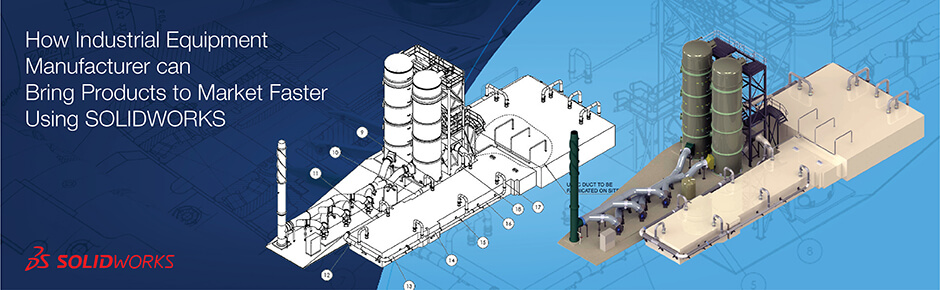
SolidWorks helps develop products for industrial equipment faster by using parametric modeling, design automation, manufacturing ready CAD models and collaborative workflows. This shortens time-to-market and maintains technical integrity and design quality.
Table of Contents
Traditional ways of developing industrial equipment products, like manual drafting and iterative designs waiting to receive feedback from manufacturing, often delay product development. These also increase costs due to increased time in the product development process.
Using SolidWorks for industrial equipment design provides a practical solution to these challenges as SolidWorks offers an integrated platform that combines all aspects of engineering, manufacturing and collaboration into one environment. By leveraging SolidWorks 3D CAD modeling for industrial machinery along with automation technologies, the development cycle of industrial equipment can also be shortened.
The integration of multiple processes enable quicker responses to customer needs while still meeting the technical requirements of industrial equipment.
Accelerating industrial equipment design using SolidWorks 3D CAD
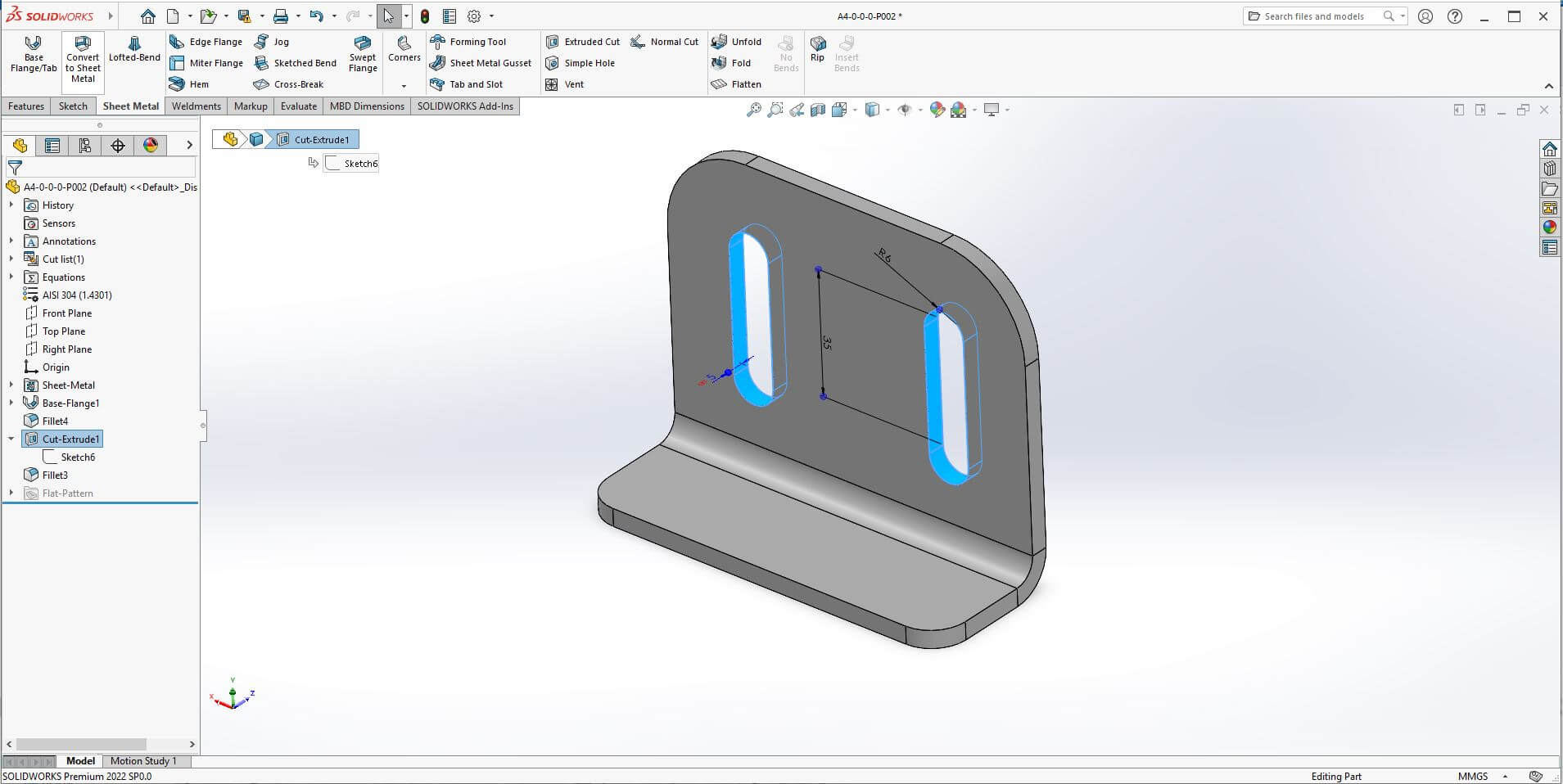
Industrial equipment designers need tools to create new products as quickly as possible while maintaining quality in their designs especially in large numbers of parts in complex assemblies.
Parametric modeling in SolidWorks for faster design iterations
Mechanical product design in SolidWorks utilizes parametric feature-based modeling techniques that allow designers to define geometric features based on dimension and relationships between them. If a designer makes a change to a key dimension, then all of the other dependent geometric features, assembly configurations and drawing configurations will be updated automatically.
For example, if a conveyor frame has to be made wider to fit a larger motor, changing the width of the frame in SolidWorks will update the location of all mounting holes, reinforcements gussets, connections to other components. The manufacturer’s drawings will reflect those changes right away, so that documentation always stays updated.
Designers can use this capability to rapidly test many design options by varying the size of structural members or the footprint of the equipment, without having to recreate the entire model. As such, this capability increases design accuracy for complex industrial equipment assemblies consisting of thousands of parts.
Custom industrial equipment configuration through flexible CAD models
Teams can create custom industrial equipment configuration using flexible CAD models through a singular master design capable of accommodating multiple product variants, capacities, and specific customer needs.
For example, a manufacturer of mixing equipment may have a single configurable model of a tank for capacities of 500 to 5,000 liters. The SolidWorks model would include parameters that are interdependent in their relationship.
This would cause the diameter or height of the vessel, agitator shaft length and positioning of the motor mounting structure to be adjusted based on the capacity selected.
The configuration table will also allow the selection of whether the unit has heating jackets, a top entry or side entry agitator, as well as various arrangements of discharge valves. For each time a customer requests a modification, the engineer can work within the predetermined configurable framework instead of having to manually recreate the entire design.
Engineering design automation using SolidWorks for industrial equipment
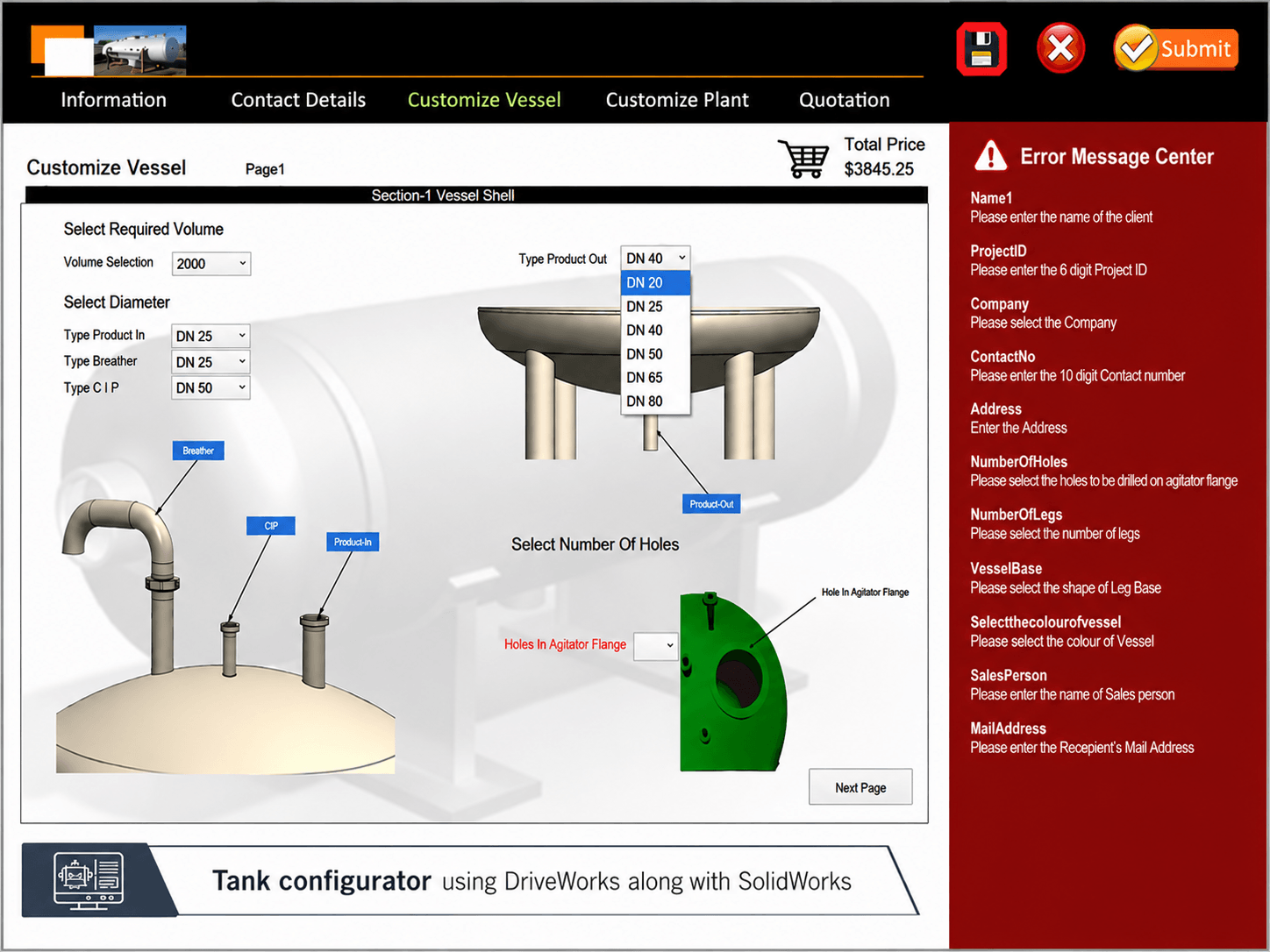
Automation has changed how engineering teams do repetitive design work and rule-based variation work on equipment designs.
Automating equipment design variants with DriveWorks
Engineering design automation using SolidWorks fundamentally alters the economic model for custom equipment manufacturing by reducing traditional engineering effort required for each order. DriveWorks design automation is an automated rule-based process that allows engineers to document their design knowledge and configuration logic.
Engineers develop design rules that govern how the geometry of equipment will respond to input parameters. For example for conveyor systems this could include the following:
- The belt width needs to be 50mm wider than the largest product dimension.
- The drive roller diameter can depend on the calculated belt tension which comes from the length and capacity of the system.
- The support leg spacing may have limitations due to structural loading conditions.
When the sales engineer enters the project parameters into the DriveWorks system, it will automatically generate a complete set of 3D CAD models that are configured for that particular application. The system generates all sub-assemblies, individual part models and all of the manufacturing drawings associated with the models.
Documentation for bill of materials are also automatically generated, listing parts with specifications, quantity and source information for the components. A task that used to take the engineering team hours to accomplish now takes only minutes.
CAD data reuse and design standardization
The use of SolidWorks in both reusing existing designs and establishing a standard improves the speed of equipment design as it allows designers to build upon previous successful designs.
A few key methods to be successful in using reusable designs in SolidWorks are:
- Making previously tested and validated parts, assemblies and templates easily available within libraries along with documentation.
- Creating modular machine configurations with consistent structural support and attachment points.
- Using validated and consistent design components throughout all product lines.
- Specifying common naming schemes for the design components and making the design database search friendly.
- Reducing engineering mistakes by using components that have been successfully used in numerous production applications.
For instance, equipment manufacturers can create standardized designs for different capacities of chain driven assemblies, validated structural frames and proven motor mounting designs. The engineering team can then quickly identify the necessary standard designs and use those as the basis of their new conveyor system design.
As a result of this strategic approach the design process is greatly accelerated while also providing the same level of quality and reduced amount of duplicated work of creating models.
2D Drawings Converted to 3D CAD Models for Industrial Tool Design
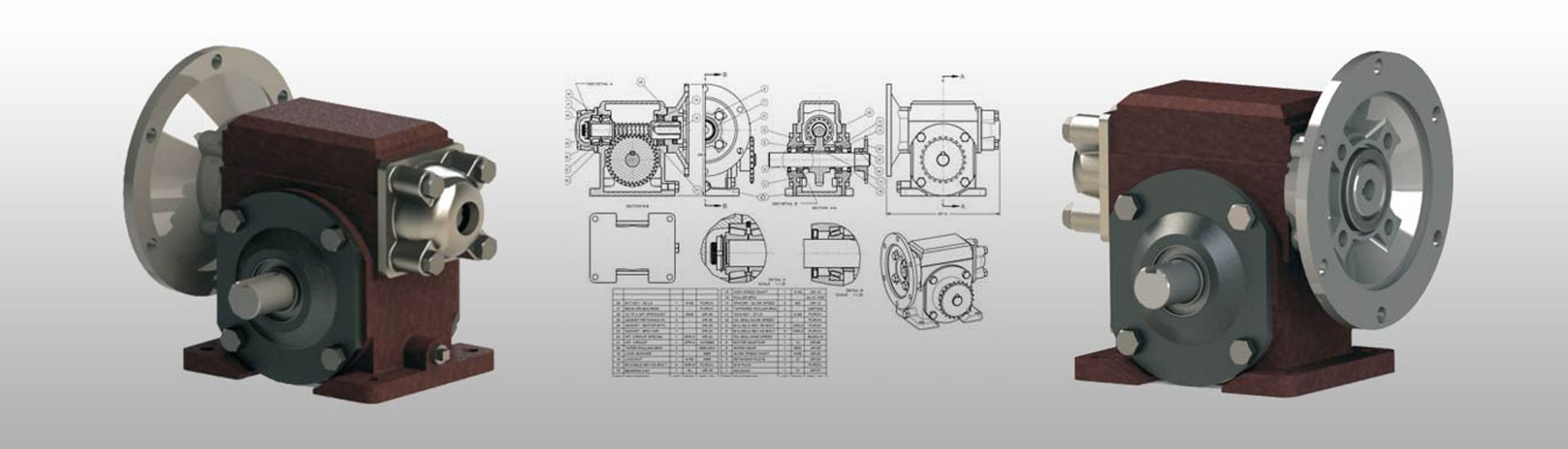
An Indian manufacturing company of industrial tools had been relying on non-editable PDF designs for its reducer gear assemblies. The inability to edit these legacy documents made it difficult to implement improvements or changes to their designs as well as to make necessary revisions efficiently and accurately.
Hitech Engineering Services reviewed the PDF drawings, as well as the capabilities of the existing shop-floor tooling, and developed a 3D CAD SolidWorks model of the reducer gear assembly. The team took the 2D drawings and turned them into precision 3D models, assemblies, Bills of Materials (BOM’s) and fabrication drawings, while maintaining the integrity of the original design.
The end results were:
- Digitized designs in editable CAD formats
- A greater ability for future design improvements
- Reduced engineering turnaround time
Creating manufacturing-ready 3D CAD models for faster production
Manufacturing-ready 3D CAD models help to move the transition of design to shop floor by inserting manufacturing data into the CAD model as part of the design process.
Shop floor manufacturing drawings from 3D CAD models provide an accurate representation of dimensions for fabrication and provide detailed manufacturing instructions. Instead of included separately in 2D drawings, 3D PMI (Product Manufacturing Information) inserts tolerancing, annotations and manufacturing data directly into the CAD model.
Key differences in how documentation is approached are illustrated in the table below:
| Aspect | Traditional | Manufacturing-ready CAD |
|---|---|---|
| Aspect Documentation | Traditional Manual drawing production | Manufacturing-ready CAD Automatic generation from 3D models |
| Aspect Change updates | Traditional Manual drawing revisions | Manufacturing-ready CAD Automatic synchronization |
| Aspect Information location | Traditional Scattered across 2D views | Manufacturing-ready CAD Embedded in 3D geometry |
| Aspect Production planning | Traditional After drawing completion | Manufacturing-ready CAD During design phase |
Using this method reduce fabrication errors caused by insufficient documentation and assist in accelerating the review of designs and reducing the time it takes to develop plans for production.
Improving engineering, manufacturing and supply chain collaboration
As solidification of products continues to grow in complexity while being produced in less time, Design collaboration across teams become a more important component.
A key element of SolidWorks PDM is that it provides centralized design data for all stakeholders to be able to obtain current approved versions of the data. This supports an integrated product development process that allows for:
- Streamlined coordination of workflow between teams including but not limited to engineering, manufacturing, procurement and supplier teams working off of the same design data.
- The sharing of complete CAD data with suppliers so they can understand the geometry, materials and assembly structure of the equipment.
- Faster feedback from manufacturing teams to engineering teams regarding the feasibility of designs while still in the engineering stage.
- Supports earlier engineering cost and risk assessment while purchasing teams are evaluating components during design.
- Allows real time design reviews where stakeholders can review and interact with the actual 3D model.
- Reduces the number of design revisions and potential delays associated with miscommunication between different groups.
Design reviews in-progress by manufacturing personnel allow them to identify issues such as inadequate clearances, fasteners that are difficult to access or components that require special equipment. All these are evaluated while they are relatively simple and inexpensive to resolve.
Conclusion
SolidWorks for industrial equipment is a full-featured solution accelerating the design, development and manufacture of products from conception to production. Parametric modeling, automated engineering processes, manufacturing ready documentation and collaborative workflow capabilities address the major hurdles associated with industrial equipment manufacturing.
The key advantage, faster time to market in industrial manufacturing is achieved by systematically utilizing these capabilities. Companies that utilize SolidWorks CAD software in conjunction with other strategic process improvements will experience reduction in their total cycle time for developing new designs as well as improve the overall quality of their designs.
SolidWorks for industrial equipment manufacturers help to achieve competitive advantages as a result of its ability to innovate more quickly and enabling you to produce products more rapidly than competitors.

 Feb 28th, 2024

Leave a Reply