
Erroneous CAD drawings have proven to be costly in terms of time, money and reputation. By being aware of common pitfalls and refining drafting practices you can save time and keep projects well under control.
CAD drawings provide foundation for product development process by assisting design and manufacturing stakeholders at every stage from concept to manufacturing. Errors in these drawings, no matter how small, when left unresolved or go unnoticed, prove to be devastating and cause huge losses.
A company manufacturing sheet metal covers for computer LCD took 15 seconds more than the average value per cover and spent USD 213,000 extra for the project. Upon root cause analysis, it was found that these losses were due to a drafting mistake as the design engineers missed considering manufacturability for the metal sheets.Source: Moldingconference.com
These errors can be avoided if drafters stay attentive to details and are trained for advanced CAD drafting techniques. Here we share some common mistakes that one should avoid at the first appearance to save hundreds of dollars later.
CAD drafting and drawing pitfalls you should avoid
1. Detail overload by excessive use of symbols
Impact: The biggest loopholes in drawings can sometimes come from misinterpretation of details when drawings are overloaded with information in the form of symbols. Details do add value and uplift design communication but too much of information in a small drawing can be difficult to read.
Solution: One simple rule is that every CAD draft should have details that are utmost important. However, if you feel that all details are indispensable, one way out is to create part drawings. Instead of creating one single drawing, break down the assembly into several components and create a separate drawing for each part.
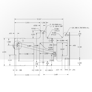 Figure 1: Detailing the drawing using symbols
For example, mounting holes, the primary feature should be shown in sketch 1, secondary features like external profiles should be in sketch 2, number of cutouts, positions sizes etc. in sketch 3 and so and so forth. The drafter should prioritize important features and put them in different sketches with appropriate annotation using symbols.
When working for a joinery manufacturer, Hitech Engineering Services’s CAD drafters created two sets of drawings – approval drawings and detailed shop drawings – for all shopfitting products and commercial joinery. This enabled seamless and transparent communication between designer and shop floor engineers.
2. Inconsistency in dimension data and tolerances
Impact: Dimensions in drawings play a major role in deciding machining operations, raw material needed, space occupation, etc. And often times, drawings are created in parts by a team of engineers. If all of them follow different systems of standards the end result deviates from the original designs, resulting in waste of time, resources and missed timelines.
Solution: Smart dimensioning in AutoCAD helps design engineers to clearly define dimensions, surfaces and shapes for 100% accurate communication of design intent to shop floor. Below are the standard ways to show dimensions of various geometries:
A) Linear dimension, aligned dimension, rotated dimensions
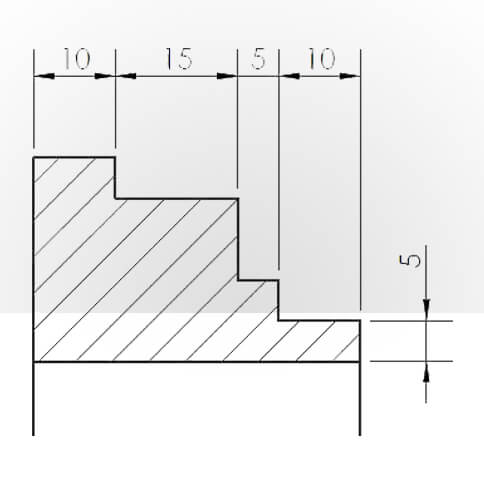 Figure 2: Dimension style: Linear
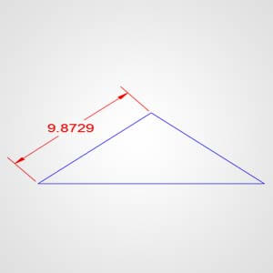 Figure 3: Dimension style: Aligned
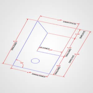 Figure 4: Difference between linear & rotated
The first one is used for the lines and distances measured along the Universal Coordinate Systems (UCS) while the latter is used for distances measured at certain angle with respect to UCS.
A rotated dimension allows the drafter to develop a linear dimension between two points that aren’t necessarily along a straight line.
Figure 4 shows all three types of dimensioning styles. Do not confuse rotated dimension as the linear dimension that has been assigned and then rotated in UCS. These dimension types clearly display orientation of the part or the assembly drawing.
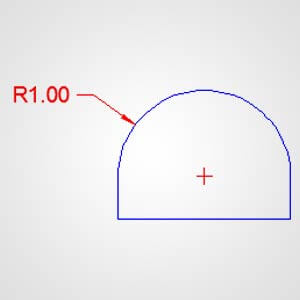
B) Arc length
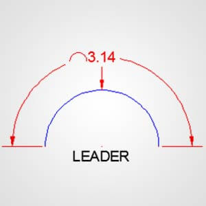
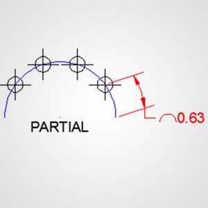
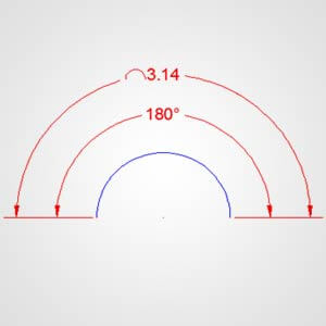
Arcs are shown using leader lines or polylines along the arc length. This feature is newly introduced in AutoCAD and may not be available in older versions. Showing the length explicitly in drawings along with the radius and other dimensions avoids manufacturing interruptions for calculation.
C) Properties of circle: Radius, diameter and center (w.r.t. UCS)
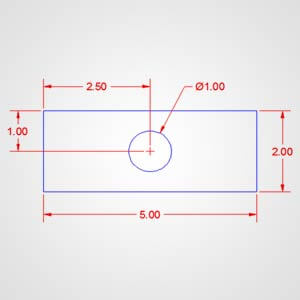
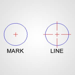
DIMRAD command in AutoCAD gives you the values for any arc type, radius and dimensions. It will also display the center mark. You can also specify if you want the mark for each circle from sub menu in dimension panel. However, in case of multiple aligned holes, it is a good practice to use a center line and extend it to other circles to show alignment and identical properties.
Images here show simple representation while the picture in real life is much more complicated. For example, a sheet metal plate will have numerous holes to be drilled. In such cases, the drafter should not clutter things up but detail it enough for clear understanding of the machine operator.
D) Even spacing, baseline and continue dimension
Even spacing, baseline and continue dimension are the three major types of dimensioning styles. They are specifically helpful when more than one distance is to be specified along a line. To show them easily, they are first put in place in the drawings and then adjusted using DIMSPACE command.
The difference between baseline and continue dimension is that in baseline method, all distances are measured from the first point known as base point. The latter, continue dimension, shows distances between two consecutive points.
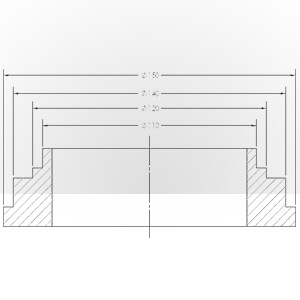 Figure 11: Even spacing dimension
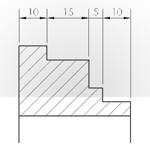 Figure 12: Continue dimension
 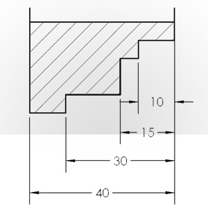 Figure 13: Baseline dimension
Guidelines go endless but it is a good CAD drafting practice to follow the rule that offers clear design intent communication and avoids conflicts. Other rules like double dimensioning, over-dimensioning etc. should be avoided; minimum spaces, visible gaps etc. between lines should be maintained consistently. Specific numbers, codes, gages etc. are to be specified with symbols and numeral values.
Hitech Engineering Services’s CAD drafters implemented a mix of baseline and continue dimensioning methods for detailed manufacturing drawings while working on architectural millwork products such as awings, railings, signage etc. The mix of two dimensioning types enabled ready calculations of even the smallest dimension and accelerated manufacturing.
3. Over utilizing or underutilizing line weights
Impact: When lines are not weighted properly, readings from drawings could be ambiguous. It leads to flawed decisions, delayed projects, and misused resources.
Solution: Line weights show relationships between two objects and hierarchies, create depth, and add clarity and legibility. To be conscious of using line weights, you must ask yourself a few questions and add the weight accordingly. Some questions include:
- Do you intend to showcase the first thing that jumps off the drawing?
- Is there a balance between light and dark in drawings?
- Is every detail clearly visible?
- Is there a consistency across drawings?
- Have you used the same line-type for different elements?
Other than this, CAD drafting techniques have some thumb rules as well. For instance, as the proximity between the line and the viewer increases, the lines get darker. So ideally, the lighter lines recede into the background.
Similarly, for section drawings, which are produced by taking a cut through the object, the element that is cut through is either the lightest or the darkest. Mid-weight lines are used for edges and light-weight lines are used for elements, textures or elements that depict details underneath the surface planes.
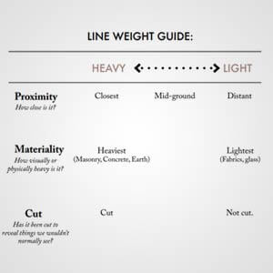 Figure 14: Line weight guide
While developing office floor joinery manufacturing drawings for a manufacturer based in the UK, Hitech CAD drafters developed drawings with
- Hatch patterns to show sections
- Dark lines, shaded lines etc. to differentiate details on the floor
4. Drawing all components in one layer
Impact: When all components are depicted in one layer, revisions get difficult. This is because when ECOs are raised, the designer marks up the drawings making them illegible.
Solution: When you draw details in separate layers, manufacturer can differentiate the objects easily. Also, it spares you from setting properties for each object. You just have to assign properties to the layer and you can control the overall plotting.
AutoCAD allows the user to hide or unhide and lock/unlock layers. It avoids unnecessary and unintended drawing alterations using the ‘Off’ button. Also, drawings can be modified easily just by specifying the layers.
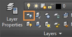 Figure 15: Layer Properties
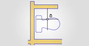 Figure 16: Locked layers
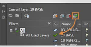 Figure 17: Current layer: Highlighted by green mark
5. Not following the model with drawing approach from the start
Impact: When 3D models and 2D drawings are not in sync or when the intricacies go unnoticed, misalignment happens. It takes you back in time to correct the manufacturing mistakes due to wrong or partial information transmitted to shop floor and increases risks of losing the contract.
Solution: The best way to avoid such errors is by converting 3D models into 2D drawings using Flatshot tool. Flatshot tool in AutoCAD projects the edges from solid 3D models to create a 2D drawing on a parallel plane. These 2D projects can be inserted as blocks in UCS and saved as drawings.
You can include any perspective you want – orthographic or parallel views. With controls such as destination, foreground lines, and tangential edges, you can select 2D representation details.
Hitech Engineering Services’s AutoCAD engineers created models for a European Stairlift manufacturer and once approved, manufacturing drawings were directly created using these approved models. Such a model-drawing approach helped the manufacturer achieve manufacturing accuracy and seamless design data exchange.
Conclusion
While these CAD drawing mistakes sound obvious, they often go overlooked when you are engrossed in drafting and drawings. By being aware and taking conscious measures, or by changing certain CAD drafting practices, these costly errors can be avoided big time.
Sometimes it so happens that drafters keep working in their rhythm and do not realize the inconsistences. When they do, it’d be too late unless they stretch their workhours. Thus, it is a good practice to follow guidelines and thumb rules or collaborate with an expert CAD team to develop CAD drawings for you.

Leave a Reply