
Table of Contents
Technically, before a processing plant is operative, a large sum of money is invested in installation and procurement of necessary machinery and equipment to setup across the facility. This calls for erecting the plant with duly checked piping needs along with controls, support and services. With the piping engineer on board, necessary designs and installation can be taken care of.
However, the need of accurate designs as per their intended need is of key importance. Today, with various computer tools such as 3D CAD modeling and 2D CAD drafting capacities have greatly improved the need to faster evolution of pipe designs abiding codes and standards. A pipe and plant layout design engineer ensures safe and efficient planning of piping network across the plant.
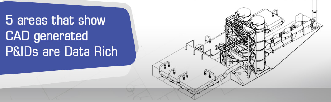
To what extra lengths do CAD drafts go for generating P&IDs?
Every P&ID project has a specific set of requirements when it comes to pipe layout design irrespective of industry. It may arise out of the geographical location of the plant, climatic conditions, specific client requirement, intended usage of the pipes and instruments and others which may have direct or indirect impact on the layout. CAD has the ability to fulfill each of these customized requirements and deliver the exact piping layout drawings efficiently. Let us look at some of the key aspects where CAD assists the designer in choosing the most suitable layout.
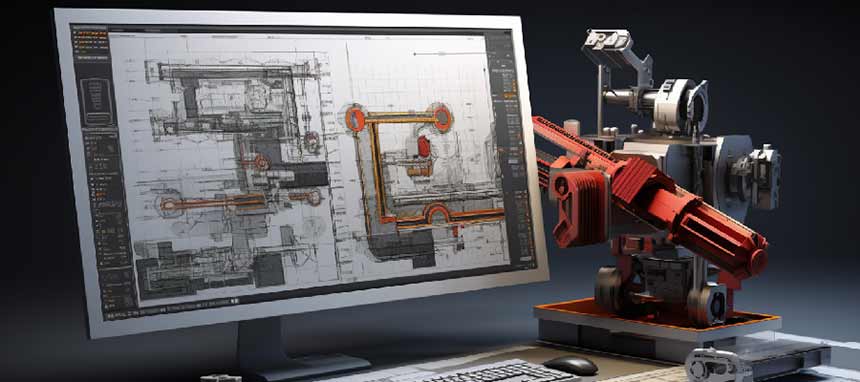
Compliance checks and BOMs with CAD
2D CAD drafts of P&IDs can be easily linked to the schematic electronic design data to perform automatic compliance checks. It allows the designs to be reviewed and checked simultaneously on a high-performance graphics. The necessary relevant documents of BOQs etc. can be generated as and when needed. Prints of the piping design can be directly obtained from the CAD generated files, including all the geometric features for the pipes and/or any other equipment.
Piping Flexibility and interference
When accounting for a number of accidents that occurred due to faulty design or placement of inflammatory substance closer to the human occupancy, the list will be significantly long. To ensure the safety, thermal expansion in pipe material is considered while designing the layout.
CAD facilitates designs in one file and allows its examination by multiple users at a time to upgrade the designs and refine for better layout. Apart from this, it is the most common phenomenon to encounter several interferences in the layout design. 3D CAD modeling provides an efficient, accurate, quick and cost effective alternative to dealing with interferences in designs.
User defined symbols in CAD library
Since P&IDs make use of numerous symbols across the diagrams, it becomes essential to define standard symbols whenever used. Especially for long term usage, CAD software allows the user to create and manage a permanent library for repetitive standard symbols, details and notes to be explicitly created.
Besides, pipes and plant layout design is followed by pipe analysis of 3D models. Part models generated act as prototypes, which when clubbed with analysis software gives accurate results without any issues of interoperability. Numerically controlled systems and other associated computer-aided analysis, quality checks, installation or fabrication needs are clubbed with the CAD models for standardized inputs.
Collaborative work approach
Since the P&ID layout involves multiple inputs from several varied disciplines, CAD offers a unique feature of a collaborative work approach on a common platform for viewing other designs. It also offers the most up-to-date information and ensures a correct flow of information through a standard channel of CAD files which was clearly lacking in sheet drawings.
Simplified solutions for replacement and maintenance
While plants need frequent maintenance and replacement of equipment, plant design engineers require the exact as-built conditions of plants and equipment within. Popular techniques like photogrammetry and laser mapping are extensively used across the industry for collecting this actual data in as-built condition. 2D CAD drafting platforms facilitate direct import of this data for conversion to digital designs in the form of 2D drafts of P&IDs and 3D CAD models of the plant.
Conclusion
One may argue that with the industrial revolution, these plant designs have become well looked after for safety and operational efficiency. However, that is not the case. Even today, there occurs a number of instances where fatal accidents happen.
Not very long ago, on 23rd March 2005, an explosion in the refinery of Texas City in the USA occurred, which caused damage worth 30,000,000 USD. The investigation revealed that one of the causes was inadequate sitting at the plant layout and fault of design in blowdown stack. Such fatal accidents compelled designers to not only design efficient but also safe plants.
This computer-supportive approach is paving new ways for project works performed and gives an advantage to the professionals in designing safest P&IDs with software capabilities. The design firms are no longer tied to same designing and documentation process and CAD provides them the opportunities to increase design productivity and safety.

Leave a Reply